
Peter Kaltenbach
If you design products long enough (regardless of industry) you will eventually need to design something involving light. We aren’t necessarily talking about specialized optics for laser systems or corrective lenses, but understanding the basic behavior of light, and how to apply it to design can go a long way in making a product work the way you intend.
For the most part, we are using light to provide either indication (status lights, etc.), or illumination, and sometimes the design calls for the solution to provide both. In either case, the design challenge is to get the photons from source, to a target efficiently. This is generally done with a light pipe, reflector, lens, or some combination of the three.
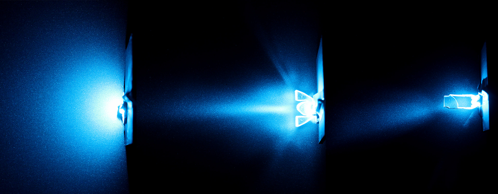
Before we jump into applying these tools in practice, it’s worth taking a little detour to understand our light sources. In most of the products we design, the source is an LED. LED’s behave differently than an ideal laser (single beam of light in a given direction) or an incandescent light bulb which throws light in all directions. LEDs are generally directional, and they are usually specified with a beam angle that can range from a very tight spot (<15°) to wide flood (>60°). In reality LEDs emit light beyond that angle, but for the sake of simplicity, the angle is limited to where the light intensity drops below a given percentage of the peak (often ~50%). You can find all this in the LED datasheet, and for the sake of simplicity, we will often represent the light as a cone, emitting from a point, centered on the LED.
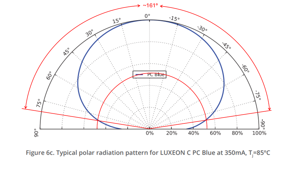
Typical LED data – Source: LUMILEDS
Light Pipes utilize internal reflection to take input light on one end of a mechanical structure and have it exit in another location while minimizing losses or un-intended light leakage. The fundamental principle behind an effective light pipe is driven by Snell’s law which describes the relationship between the angles of incidence and refraction. We learned in school that when light crosses the interface between two materials of different densities, there is a change in velocity that leads to refraction. Snell’s law gives us the tools to apply this in design. When the angle of incidence exceeds the critical angle all light is reflected within the material, and this “Total Internal reflection” is the fundamental principle behind light pipes.

Snell’s Law: Refraction, Critical Angle, Reflection
Snell’s law can also be used to design a method of projecting light for illumination. Raytracing based on angles of incidence, reflection, and refraction can help you predict where light will fall when exiting a transparent surface (basic lens design).
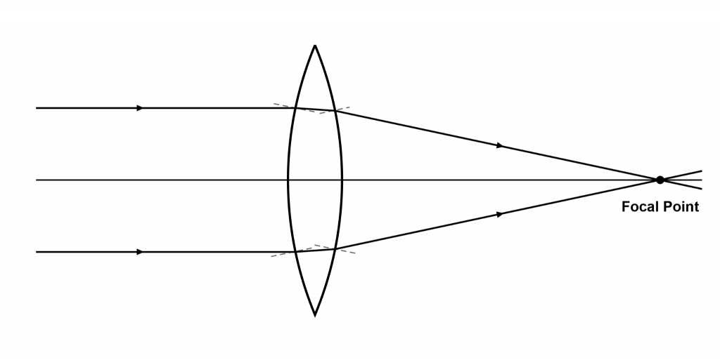
Refraction through a biconvex lens
We have a few options (of increasing fidelity) to bring all this information together, and evaluate the impact in a design. At Pump, our first pass is a basic geometric analysis in CAD. Tracing rays at the extents of the LED’s beam angle can give a good approximation of how light is going to travel through a transparent part. For more complex behavior (such as trying to straighten the rays of light) more data points can be traced, and through an iterative process a lens shape can be developed.
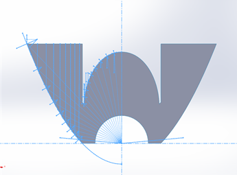
Custom Collimating Lens designed in SolidWorks straightens rays of lights into a narrow directional beam
To validate a design prior to prototyping and production, there are a number of really well featured CAD plugins and standalone software that can provide quantitative simulations. These can predict light intensity, color shifts, and focal points. Programs such as Photopia, TracePro, and others are great tools, but often more than we need for early qualitative predictions. When we were unable to find a good middle ground, we developed our own 2D raytracing application that allows us to import a DXF or SVG (of a light pipe or lens) and create a good approximation of how it will behave. You can experiment with it here: https://toolbox.pumpstudios.com/
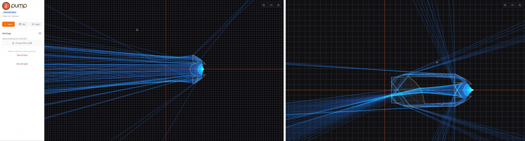
Simulation of lenses with Pump Lightpipe Demo
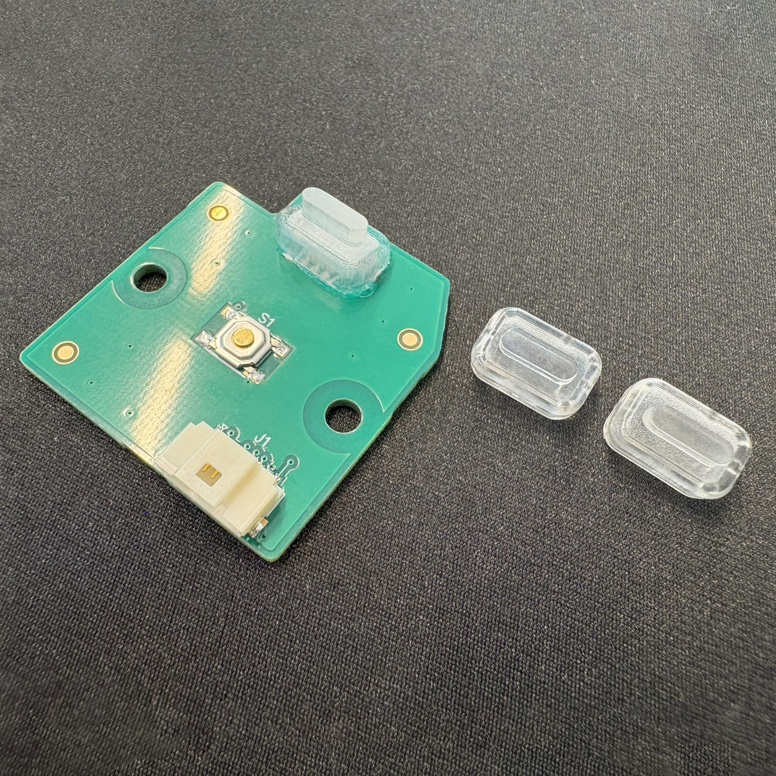
If you’ve read any of our past posts, you know how important physical prototyping is to our process. Lighting is no different. We always start as simple as possible and work our way up to a high fidelity prototype of the final design. For lighting applications we often start out by cutting a 2D shape from sheet acrylic. The laser provides a polished, reflective cut edge and allows us to test and iterate on geometry quickly. Likewise, using heat to bend sheets, or 2D patterns can literally add another dimension to our test. Finally, when we feel reasonably confident in a solution, we will progress to polished CNC, or waterclear SLA parts which allow us to test the solution in context of the full assembly.
A quick cautionary note, pay close attention to the material properties of your prototype, and final production parts. Transparent materials have different indices of refraction, and this can significantly change the behavior of a lens or light pipe (water clear SLA materials are generally between Acrylic and Polycarbonate). Likewise, the wavelength of light has an impact on refraction as well, so if you are designing for a specific color, or range of colors, it’s a good idea to check. Our 2D simulation allows the user to change the wavelength and see the change in light behavior for just this reason.
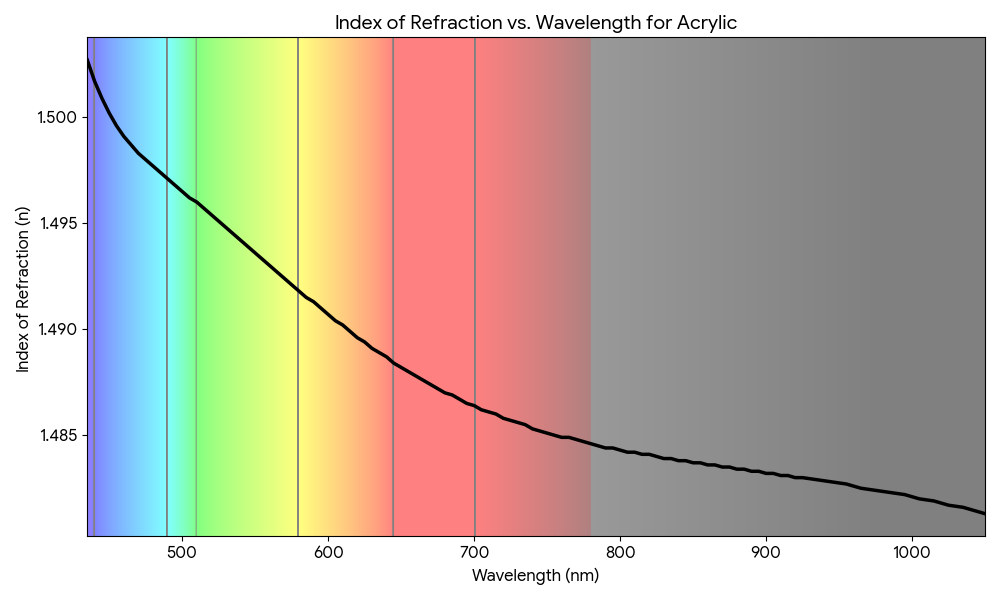
Refraction vs. Wavelength – Acrylic
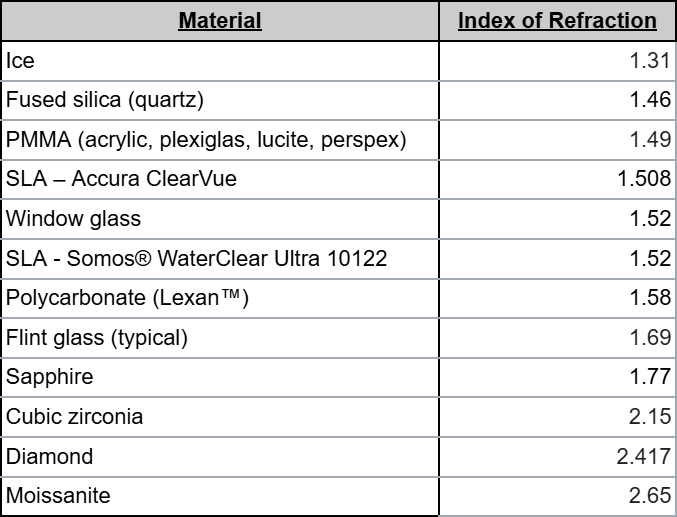
Index of refraction of various solids
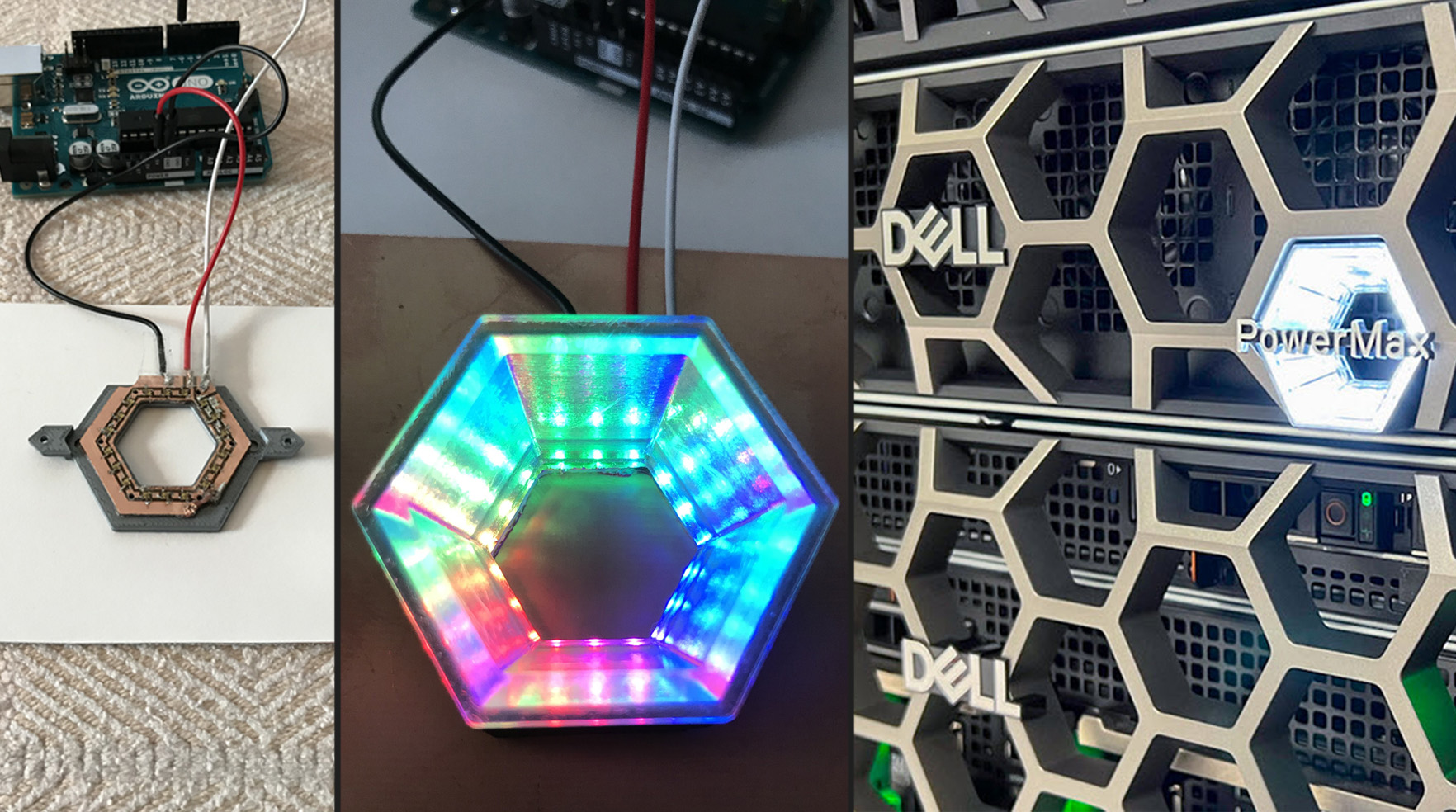
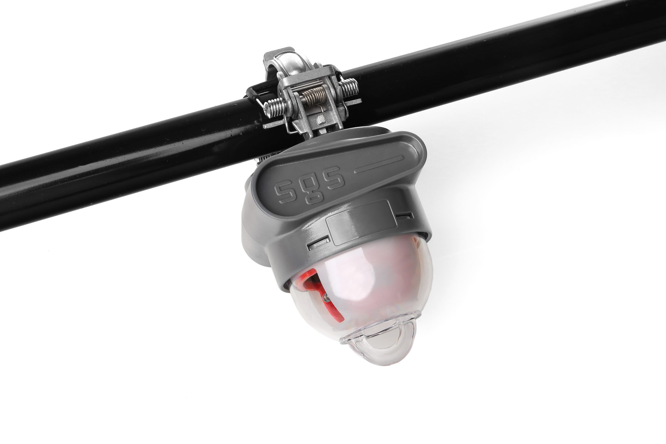
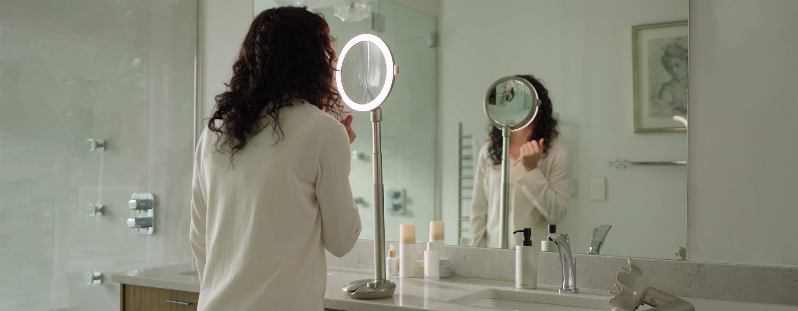
Over the years we’ve applied these techniques to a range of problems. User interfaces (Dell Enterprise), Illumination (MirrorGlow and Merchsource mirrors), to high visibility fault indicators for overhead power lines (Smart Grid Solutions). Do you have a challenging optics problem to solve? We would love to hear from you.