
Jack Moranetz
Designing and optimizing a gear train can involve a lot of moving parts (literally!). From managing competing design constraints, to a pile of engineering guidelines and best practices, it can feel like a daunting task. Recently, we developed the AccuQuilt GO! Bolt, and faced all of these challenges. At each stage of the process, we learned valuable lessons that helped lead to a successful final outcome. Follow along for our process and be sure to check out our top 10 tips for designing a gear train below!
(Proof of concept)
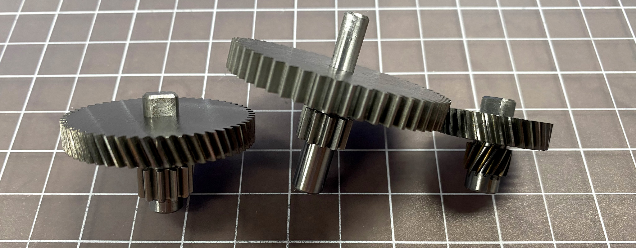
As with most projects, this one started with a proof-of-concept prototype (POC). We built a functional test platform to test our assumptions. The GO! Bolt is a roller die cutter for fabric, and one key question was how much torque would be required to cut through our target cotton material. With the POC prototype we were able to measure the torque required to cut in different scenarios, as well as test different motors. The platform was successful in these aspects, however we noticed that the gear train was very complex and loud (mostly a result of the huge gear reduction (930:1) and metal gears).
(Prototype 1)
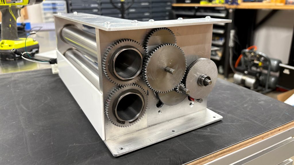
Armed with well defined torque and speed requirements, as well as our observations from the POC prototype, we moved on to Prototype 1 (our first full prototype). At this stage, the gear train was spatially constrained by the industrial design and we understood how fast the cutter needed to run. We also hoped to reduce the gear noise significantly. To start, we identified a lower speed, higher-torque motor. This new motor lowered our total required gear reduction to 300:1, which enabled us to eliminate an entire stage of the gear train. Prototype 1 performed mostly as expected, however it was still louder and the output speed was actually faster than expected. We came to understand that the real-world speed was a result of a variable torque requirement, making it difficult to predict. However, we realized that looking at the average torque over a cutting operation was a much better metric for speed (another reminder of the importance of prototyping!).
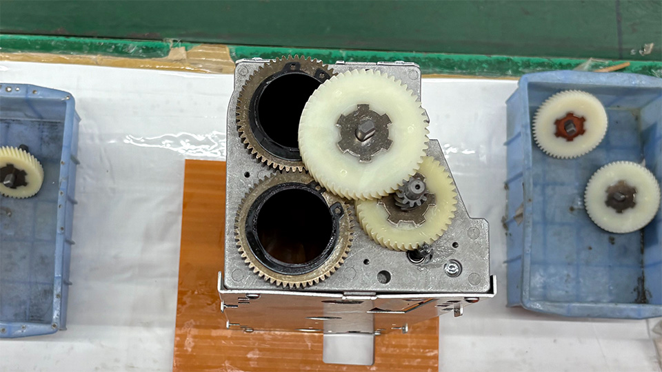
(Prototype 2)
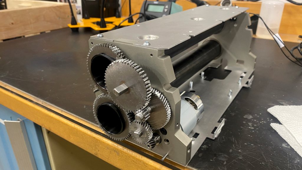
In designing and testing our next full prototype (Prototype 2), the two major priorities became reducing noise and ensuring the design was manufacturable. This time, we began to work closely with the contract manufacturer to source an even slower motor; one with a torque curve that better matched our requirements. We also made a large number of tweaks to reduce noise. Critically, we made use of helical gears wherever possible. Helical gears can also achieve larger reductions, allowing us to remove yet another stage. We also converted metal gears to plastic where possible and swapped roller bearings for bushings to further reduce noise. This prototype was built to validate manufacturability, so all of the components mimicked the planned production process. The prototype performed well. The output speed was finally correct and the sound was significantly improved.
(Production unit)
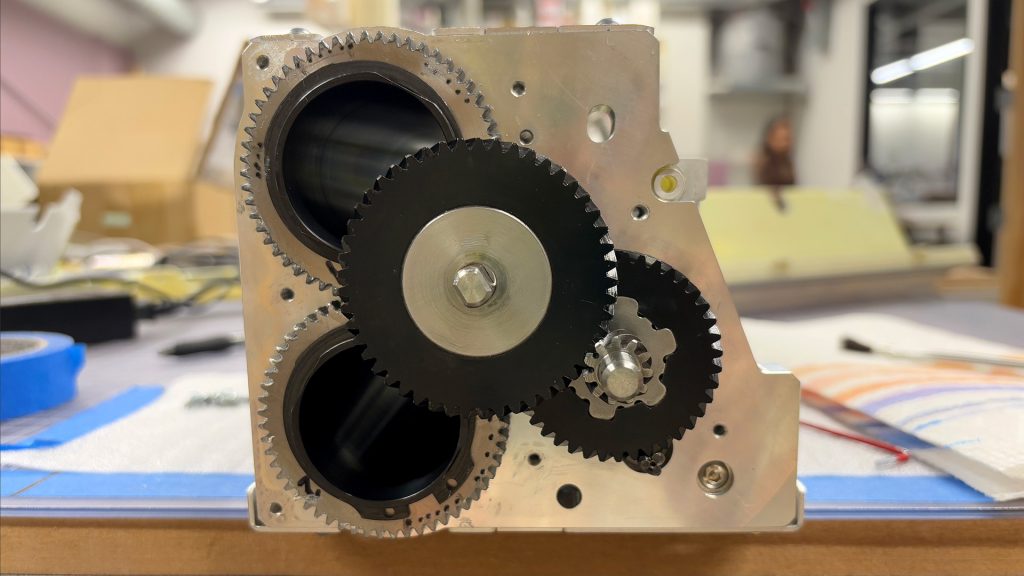
In preparation for mass production, a few final tweaks were made to address design-for-manufacturing (DFM) feedback from the contract manufacturer. The overall gearing strategy remained the same with only slight adjustments to maximize gear strength where possible. When the time finally came to evaluate production samples, our job wasn’t finished and we were continuing to learn. The cutter performed very well, but we found some variability in noise between individual cutters. After assessing the issue, we defined and tightened critical tolerances and tested a range of different lubricant options to improve the product further.
It’s rewarding to reflect on how each iteration brought new insights. By applying what we learned and adhering to established design principles, we arrived at a successful final result.
Reflecting on the project, we’ve identified a set of our top 10 practical guidelines we’ll carry forward to our next project. We hope that you will find them valuable as well!


